Heathkit DX-40 Page
The continuing saga of the DX-40...
January 2023
I put this project aside over a year ago to work on several other project but now I'm back. Some of my false starts are way down below.
I reacquainted myself with changes I had made to the audio circuit and decided that I had to try the thing out on the air. I called a local ham I knew and asked if he would listen on 40M to see if I had successfuly built the modified audio circuit. Alas, I was told that there was significant humk and weak audio. Ugh! I had completely changed the modulation portion of the DX-40 and had, evidently, screwed it up.
Looking over the wiring, I wasn't pleased with my workmanship. I cleaned up some of it and relocated some components to try and address the hum issue. The circuit called for a negative bias supply and I had used the tried and true method of using a small filament transformer wired in reverse (taking the 6.3VAC as into the output leads and getting 120VAC from the primary). I relocated this transformer further away from the 12AX7 preamp, placed a copper shield between and hoped that this would help with the hum. Nada.
I decided to make a fresh start. Below are a couple of schematics from N1UVI. I went with the "hifi" version and incorportated it into the DX-40 schematic to make it more clear to follow. The complete schematic is below, with the modifications in blue. The negative bias on the 6146 should be adjusted to about -80VDC.

-----------------------------------
.....previously... things that didn't work very well.......
The intend is to make the DX-40 an AM transmitter only, so the PPT relay isn't intended to make the antenna changeover for CW. I made the following changes:- Added an 8-pin mic jack to replace the existing jack. I used an 8-pin mic connector because my D-104 was set up for a Kenwood transceiver and I didn't want to fool around with adapters. I only use the mic and mic ground, and the PPT and PPT ground, so 4 connections.
- Added another SO-259 antenna connector for the receiver
- Changed line cord to 3-wire
- Added a fuse on hot line inside the chassis
- Added a 6VDC 4PDT relay controlled by PPT switch on D-104. Attached with double-stick tape.
- Added a 1meg potentiometer in place of the ground screw on rear of chassis. This would afford some audio gain control with the the amplified D-104. IWA1QIX on the
- Changed the VFO RCA jack to a BNC jack. I had to rotate (90-degrees) the two-terminal strip that holds the 0.5/600V cap and the 10K/5W resistor in parallel. This to make room for the relay. A new, longer wire to pin 2 of the Function Switch was required.(image below)
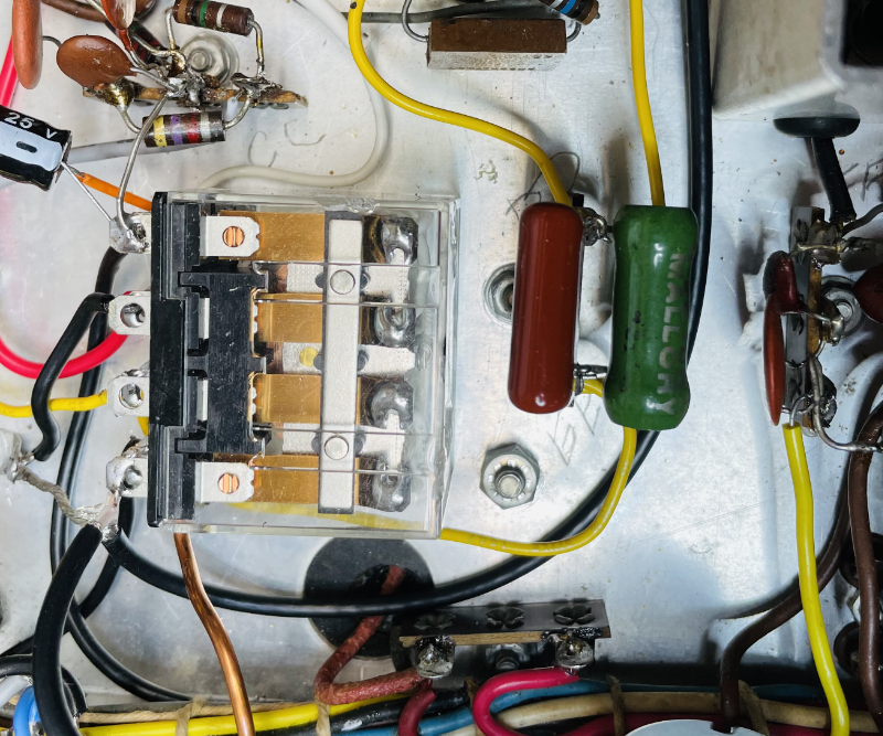
Relay attached with double-sided tape. To the right, two-terminal strip turned to make room for relay.
Added a fuse holder mounted on a small "L" bracket to both use the existing transformer mounting screw and to move the fuse away from the "40 METER" coil on the 6CL6. The "L" bracket also allowed the fuse holder mounting screw to clear the chassis. I used a 6-terminal strip (on the right side) to attach the line and transformer leads.
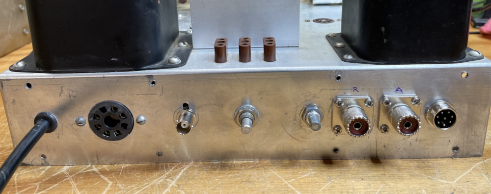
From the right: 8-pin Mic jack, antenna jack, receiver jack, 1meg pot (currently unused), crystal/VFO switch, VFO BNC jack.
Actually, this didn't work very well... So I just got things that now do seem to work and will post what I did soon...
Audio Mod
Well, after all that the relay seems to be working and I can tune up in CW, but I'm only getting about 50ma max on the voice peaks on Phone (manual suggests at 125ma on peaks). I carefully traced out the audio section and found it was not consistent with the manual schematic. So I think I will take apart the audio and rebuild it with one of the modifications others have used on this or similar Heathkit transmitters.
There are a number of audio mods but most are for the Heathkit DX-60, similar in many ways to the DX-40. The problem (for me) is that many of these require a negative bias supply, something that I would have to find room for under the DX-40s chassis.
Looking around the web, I found several sites suggesting the use of a small filament transformer connected in reverse, that is, using the 6.3VAC secondary winding as input from the filament line in the transmitter, and using the primary as output with about 117-120VAC rectified for the negative bias voltage. Searching through the junk box, I found I have a nice small filament transformer that can fit by moving around a few other components. Rebuilding the audio section anyway, will allow me to make space (I think).
....... Found a schematic from WA1QIX on the amphone.net site.