Amateur Radio - N2IFV
I don't have a lot of ham radio equipment at this point. My interest lies in making my own rig and especially in working on the older vacuum tube transmitters and receivers. I guess some of us romanticise about the "old days" and want to relive them through our hobbies. I plan to eventually get on the air when I've completed a decent vacuum tube station. My recently refurbished Hallicrafters SX-101A is a step in that direction.
Beginnings
I haven't held a ham radio license in quite a few years. But I my passion for radios and electronics started at the age of 15. In 1960, I earned a Novice Amatuer Radio license (WV2LWW), which was only good for one year. The Novice license permitted morse code work on parts of the high frequency bands and voice on 2 meters, up near the frequency used for some television stations at the time. I didn't have the equipment for communicating on 2 meters, but I did manage to borrow a 2 meter Gonset Communicator once in a while from a ham down the street. Hams are notoriously kind to young kids interested in the hobby, and I am grateful for the help I got. I was not very proficient with morse code and got frustrated with both poor reception and the abilty to keep up with the code I was hearing. I think that I was not very interested in practicing, sort of like I was with the trumpet.
In 1961 I took the Technician Class exam (at that time it was the same written exam as the General Class exam), passed the theory part and passed the Technician Class code requirement, still able to copy 5 WPM. My new Technician license (WA2LWW) allowed me to operate voice on 6 and 2 meters, and the license was good for 5 years.
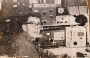
My memory is a bit vague on this, but as I remember it, my dad had heard about a ham who lived a few miles away that was selling a homebrew 6 Meter transmitter and a receiver converter very cheap, and he helped me buy it. I was 16 and it was like Christmas! (see photo above)
On the air with the new 6 meter station, I came in contact with a couple of nearby college students who were pursuing electrical engineering degrees at Newark College of Engineering (now NJIT). This group had convinced the owner of a TV-Radio repair business to let them use part of one of his out buildings to create a radio shack. Not only did these engineering students become good role models and teachers, but they were also patient with a young kid who wasn't yet old enough to drive. I learned a lot from them and I will be forever grateful.
I lost interest when I went to college and my Technician license lapsed. Fast forward to 1988. I again received the Technician Class license, passing the 5WPM code requirement by listening to morse code tapes during my commute while teaching at Trenton State College (Now the College of NJ). I didn't become very active and again let the license lapse.
During the first pandemic summer in 2020, I took both the Technician and General Class license exams (they're now different) and passed. No code requirements now, and I'm not sure how I feel about that. Ironically, I'm working on learning code again using the Koch Method . With this method, you learn code at (what I would consider) higher speed - 20WPM, starting with two letters and increasing one letter/number at a time as you progress. I'm getting there slowly. And, because I had had a previous call sign in the 80's, I was able to apply that call sign again to my new General Class license.
In July 2023 I took and passed the Amateur Extra license, so now I am legal to use on all the amateur bands.
Below is some of my work to make my own or restore older ham equipment.
Homebrew 6 Meter Transmitter (Fall 202)
The 6 meter band has, for some reason, always been fascinating to me. The idea that it sometimes "opens", sometimes it is just static seems a bit like Brigadoon. Anyway, I was looking for my next project (I just finished a dining room table that took nearly 7 months. Yes, I'm slow.) and searching early copies of 73 Magazine I found an article in the August 1965 issue by Robert Ruda (W2BHT) about building a relatively simple AM 6 meter transmitter. I suppose I should think about a SSB rig but I guess I'm just partial to AM. And they are simplier to build!
I've redrawn the schematic and added a simple power supply. I did have many of the parts for the transmitter and power suppl/modulator and that contributed to the decision to build this. But before actually starting the project, I searched ebay for some of the critical parts I did not have. I had one of the B&W miniductors but needed the other (I guess I could have made my own but I've only had moderate luck with that.). The slug tuned oscillator coil was not available but I had a few, so using my handy MultiFunction meter
 I found one that was close the to 2microH value. I also needed a modulation transformer, but that is always a functon of watching ebay for one at a reasonable price.
 I had a lightly used 7x9x2 chassis that I used for the transmitter and bought another for the power supply and modulator. I started with the tube filament wiring and mounting the variable caps and connectors, although I always forget something.
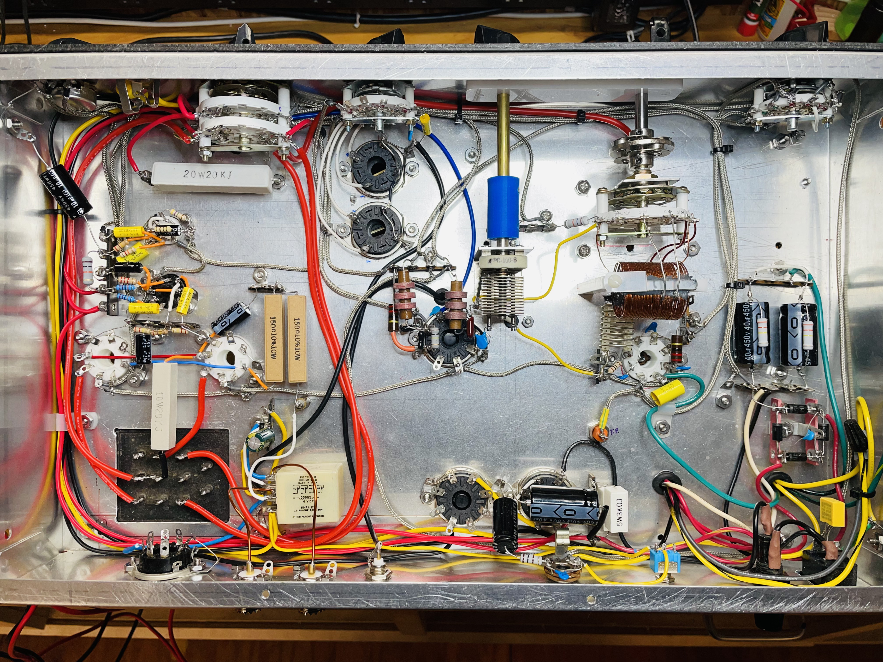
 This photo is of the finished wiring of the transmitter secton. Separating the PA from the oscillator and multiplier/driver was something I had not planned for as can be seen. So far, it hasn't been a problem. But I think I can squeeze in an aluminum separator if I really need one.
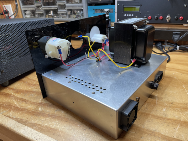
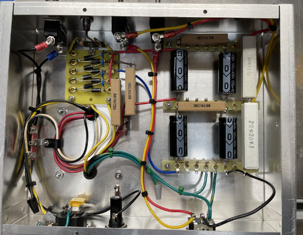
 The power supply and modulator chassis is shown here. Note the bridge recifier that I did not actually use. I thought about the additional voltage but decided that I would keep the roughly 300 volt supply (under load), so only two of the diodes are used. Get the power supply working then tackle the modulator.
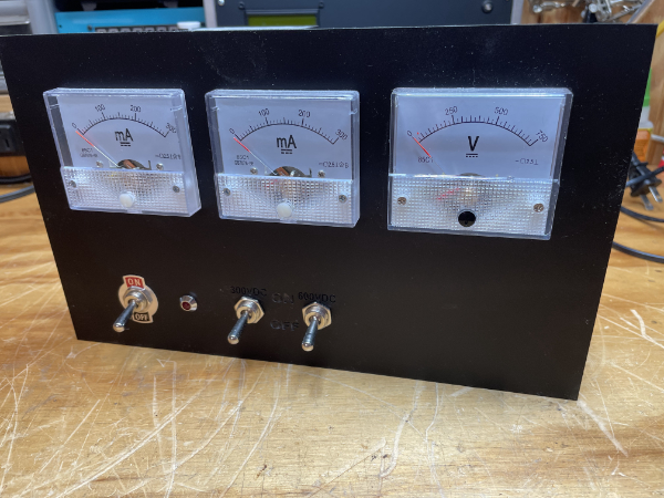
 The transmitter mounted to the rack panel. I like the "retro" look of the round meters. So far, the transmitter is putting out a signal on 6 meters. I'm waiting for the 6DT5A tubes (substitues for the 6CZ5 tubes) to test the modulation of the signal.
Homebrew HF Tube Transmitter (Fall-Winter 2021)
I've wanted to build my own transmitter for a while now and have been searching for a circuit that would allow me to use the Kenton T-493 40-Watt modulation transformer I bought on ebay in the late summer (2021). Sometimes I look at what's been newly posted in a few categories: Heathkit, Hallicrafters, and some of the other name brands that were popular in my younger days. And sometimes I look for harder to find components that may lead to a new project. Such was the case with the Kenton. Modulation transformers are hard to come by and usually quite expensive. Using PicClick, a search engine for ebay, I found this transformer that had been posed 5 minutes before and it was "Buy Now" (instead of bid now) at a reasonable price. So I bought it, not having any immediate use but hopefully would lead to something in the future.
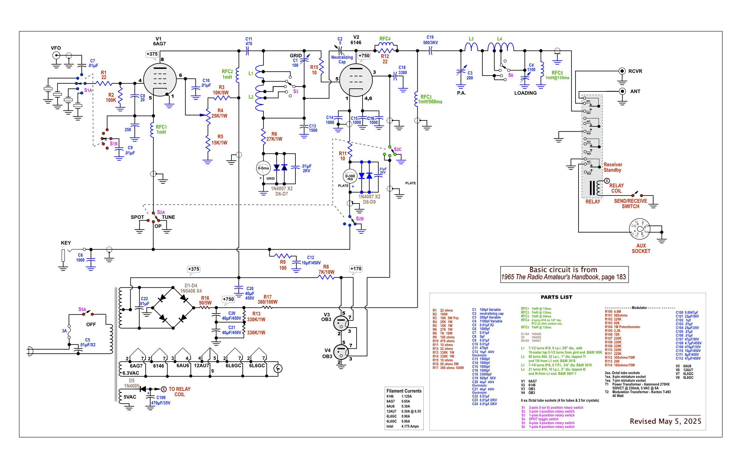
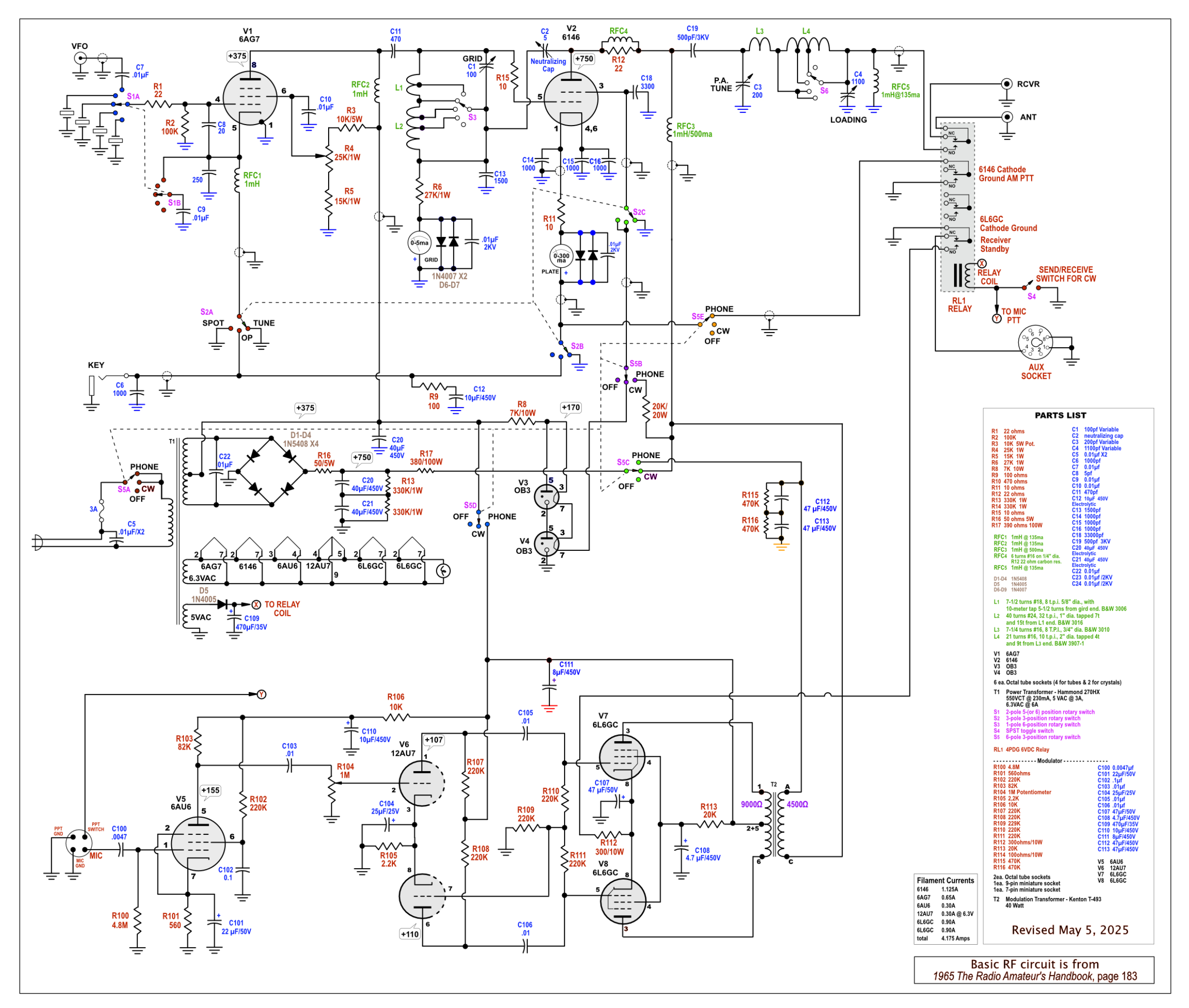
My internet search for an appropriate (for me) circuit didn't lead to any that I was crazy about. I looked in some old ARRL handbooks and found a likely candidate in the 1965 edition of The Radio Amatuer's Handbook (page 181). However, this project had a screen-modulation circuit, and I wanted to use my Kenton transformer for a plate-modulated final. But most of the other specs seemed perfect. The 40 Watt transformer would work well with a 75-Watt transmitter. I had a couple of 6146 tubes and many of the other parts needed, although I knew I would have to make some changes and experiment a bit to meet my expectations. Some parts would be expensive to purchase and I would probably need to use some substitutions.
Below is my working schematic. I redrew the original, in part because that allows me to pay greater attention to the circuit and helps me to better understand what is going on. This schematic will be has as been revised as I build the transmitter and find my errors and revise the circuit with the results of testing. But it's a good starting point.
Also, the modulator part of the schematic is taken from Joel Gonzalez's Homebrew AM Transmitter on his "backyardastronomy" site.(THIS IS AN OLD VERSION THAT WAS UPDATED JUNE 2025 - SCROLL BELOW)
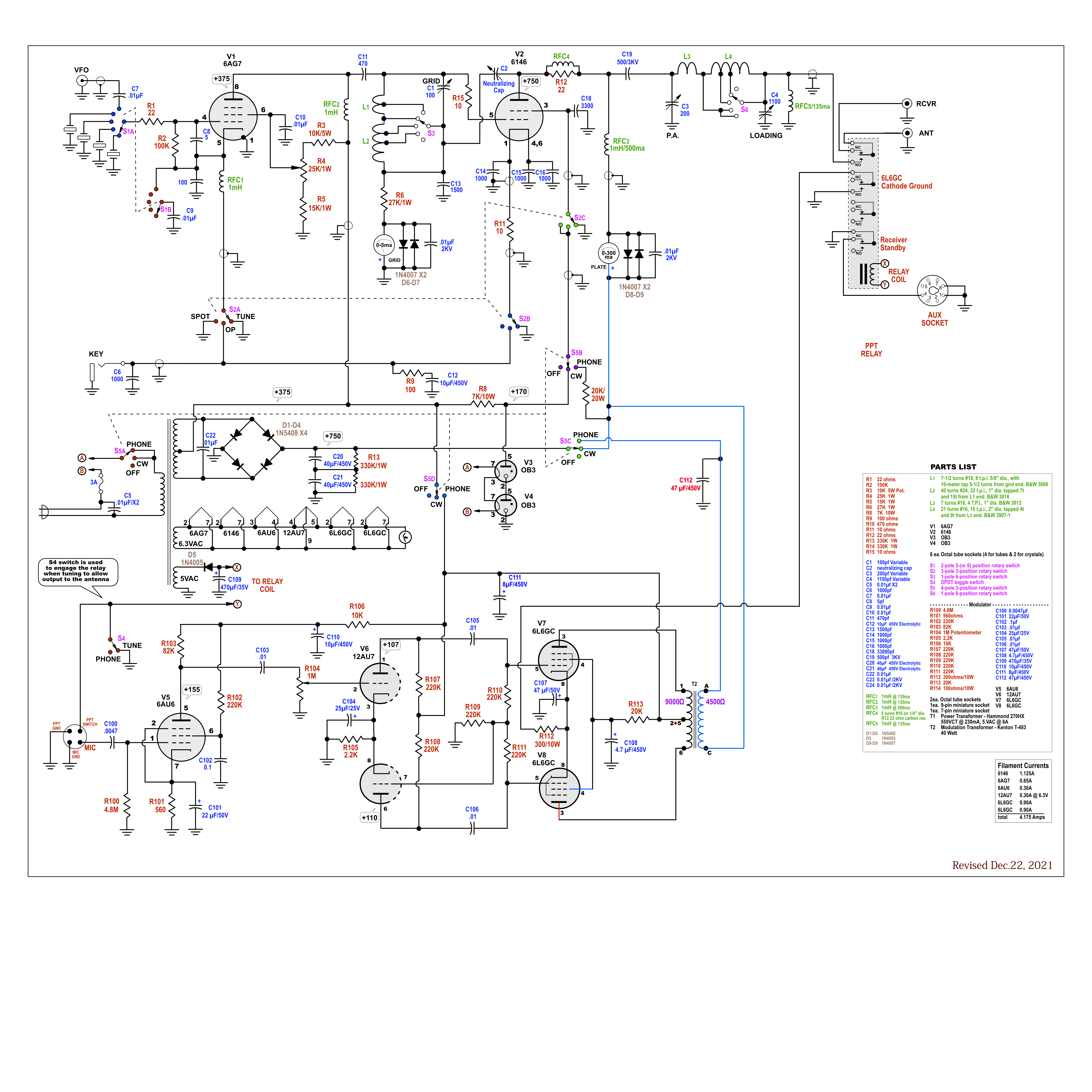
The color codes for the rotary switches on the schematic: I used some Sharpies of different colors on various switch poles that helped me keep the circuits straight.
I'm committed to using one power supply for the transmitter and modulator. We'll see how that works. I built a prototype test modulator circuit using this circuit. I will see if the power transformer I am using is up to the task of powering the modulator as well. It is adequate for the filaments at 6Amps.
I decided on two meters instead of switching grid and plate current readings on one meter. It's only money.
I've added a PPT relay that will ground the 6L6GCs cathodes, as well as used to switch a receiver to standby on transmit and change antenna from receiver to transmitter. Also, I'm not sure about switch S5B (OFF/CW/PHONE). It bypasses the regulated voltage to the screen, but logic says (at least to me) that there needs to be a bit of modulated voltage going to the 6146 screen on AM. A little knowlege is a dangerous thing and I will probably need to ask for some help with this part.
I did change rotary switch S5 from a 3-pole to a 4-pole. That 4th pole allows me to switch off the B+ to modulation transformer/6L6GC plates when in the CW position.
One of the challeges was going to be the coils specified in the handbook circuit. An article Homebrew Your Own Inductors! by Robert H. Johns, W3JIP, provided really good ideas and techniques, so I decided that I could overcome the scarcity of those B&W inductors. My first attempt to "roll my own" is shown on the left. One bit of advice though, don't use acrylic as the epoxy doesn't stick as well. The large neat coil I did find on ebay at a reasonable price (B&W 3907-1).
I had a used 16"x10"x3" chassis I picked up at a swapmeet that I hoped would accommodate the modulator circuit as well as the RF circuit. It was lightly used and didn't have too many holes. The square hole on the left side of the chassis is for the modulation transformer.
The two octal sockets aligned vertically near the top are for the FT243 crystals. The two octal sockets in the center bottom of the images above are for the 0B3 voltage regulators. As well as connections for voltage regulation, they have an interal connection between pins 3 and 7. I read somewhere that this can be used to make sure that these tubes must be in their sockets to complete a circuit so that higher, unregulated voltage will not damage other parts if the tubes are missing. Seemed like a good idea, so I incorportated that into the transmitter.
The adventure continues...
November 18, 2021
300mA meter arrived yesterday and was immediately installed. I would like to get the RF portion working before doing anything serious with the modulation circuit, although I did wire the 6AU6 and 12AU7 audio amp and phase inverter. The power supply and voltage regulation system works. The 6AG7 oscillator is working (yay!). I substituted a 4-pole, 3-position rotary switch for S5 because I think I might need a way to disconnect the modulator B+ when not in use.
Questions: I still haven't figured out how I will incorporate a PPT system.
Will I need to shield the audio section from the RF section under the chassis?
I'm going to shield the topside RF section, but I don't know where the shield will go. There's not much room between the 6146 and the power transformer (poor planning!).
Will I need the separate power supply for the audio system shown in the schematic above, or can I use the RF power supply? The power transformer is capable of 230mA, but is that enough?
December 3, 2021
I built the RF shield using suggestions from Mike Bohn, KG7TR. He has a webpage devoted to building techniques
Tips for Homebrewing Vacuum Tube Radios that is very useful! And the examples of the projects he has built are as impressive as they come.
As is apparent, I haven't mounted the modulation transformer because of the additional weight that would make it more difficult to move the chassis around.
Above: The accessory octal socket is on the right rear of the chassis. The BNC jack is for a VFO.
I am getting RF output from the final 6146 and 3mA of drive on all bands except 10meters (about 2.3mA). Using only a 60Watt light bulb, I can get it quite bright but haven't as yet put a wattmeter on it to see what the output is. The 6146 I have is weak on the tube tester so I have another one coming from ebay.
Below: The PTT relay is lower left.
December 8, 2021
The audio amp (6AU6) and the phase inverter (12AU7) are working, so it's time to mount the modulation transformer and complete the audio circuit.
The rig now seems to weigh about 30lbs, so moving it around on the benchtop is becoming a challenge.
Above Right: The thick red wires are for the 750VDC. I am hoping I don't have to use shielded wires for those runs, although I have used the 22AWG shielded wire for some of the other shorter runs, so maybe that would be ok. But I bought the 3KV wire because I thought that would be safer for these B+ runs. Not all the wiring for the audio stage is complete in this photo, but I'm getting there.
Some of the ceramic resistors are a bit of overkill, but they were the ones I had of the right value.
December 24
Got the rest of the wiring of the modulator section completed and now it's time to test the push-pull output of the 6L6s, but first will recheck all wiring to avoid surprises. Then, I need to protect the output of the modulation transformer with a load.
May 2025
While the transmitter worked, it had a serious condition that required re-tuning almost every time it was put into transmit mode. So it had been sitting on a shelf (very strong shelf) for some time, I decided to dig it up and try to, again, troubleshoot the proble.
After some hours of unsuccessfully solving the problem, a complete rebuild of the oscillator and PA sections seemed the only solution. I had trouble with the original oscillator circuit so it was changed just a little. These and other changes are reflected on the schematic below (click on the image for higher resolution). Also, to keep things simple, only the CW portion was rebuilt. I will get to the phone ciruit when all is working as it should in the basic transmitter.
JUNE 2025
On a dummy load, the output is about 40W. I put a couple of resistors in the power supply circuit to curb the voltage for a bit while trying out the circuit. They will probably be removed if all goes well.
I wanted to try out a way to label the controls by using the Glowforge laser cutter/engraver. If the laser could remove the black paint on the 19" rack panel, then the bright aluminum should show through. The tricky part for me was getting the alignment right. I've mentioned before that I use Affinity Designer to develop vector files for the Glowforge and the software seems to do a good job of accurately producing results that are true to scale. The Glowforge has a centrally mounted camera in the lid, so anything off center is distorted by the "fish eye" lens, so aligning the engraving file with the panel in the laser is something I have not quite mastered.
The result are below. Not too bad but the "Y" alignment should have been moved down a bit, as can be seen in the RECEIVE / TRANSMIT label and the 1-10 dial markings for some of the controls.
Heathkit MT-1 "Cheyenne HF Transmitter
I found the MT-1 at a swap meet in early summer 2021. This transmitter was manufactured around 1959 and was in fair condition cosmetically. It did not come with a power supply. The power changeover/antenna relay was non-functional, but the manufacture is still in business and I found a similar relay to replace the old one. Of course I replaced the old electrolyics. I have gotten only a modest power output so I am still working to get it up to specs.
MT-1 Power Supply
I kept my eye on ebay but sellers were demanding high prices, so I decided to build one myself. The power requirements for the MT-1 is 500-600VDC @ 150mA, 300VDC @ 100mA, and either 6.3 or 12.6VAC. I used a Hammond transformer with a single high voltage and filament windings and a circuit that would provide both high voltage DC outputs required.
\
\
Hallicrafters SX-101A Ham Band Receiver
I saw the SX101A on ebay at a good price that included free shipping. The ad said it had some issues but from the photos, looked in pretty good shape overall. The dial cord would need to be replaced, which required removing the front panel. There are a couple of "how to" websites that show what others have done to rennovate this particular receiver, so I got some good pointers from them. There was also a four-part series in Electric Radio Magazine (2005: September, October, November and December) that was very helpful. Back issues are available for purchase.
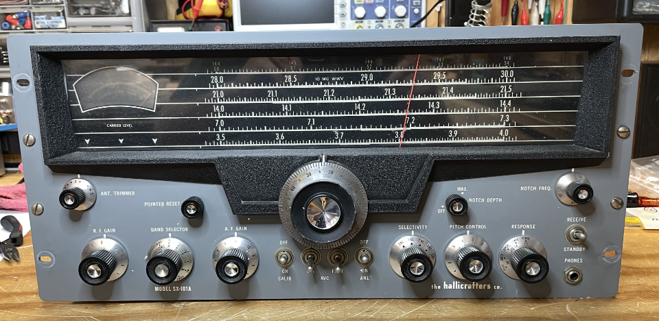
As you can see from the pictures, there is no evidence of rust. The chassis, supports and cabinet are steel and it weighs in at 75lbs. That's why they are called "boat anchors." The SX-101A was one of the best ham receivers in the early 1960's.
Besides installing a grounded. 3-wire plug, the 50+ year old paper capacitors needed to be replaced (Left). Part way through replacing paper caps with those yellow polyester film caps (Right).
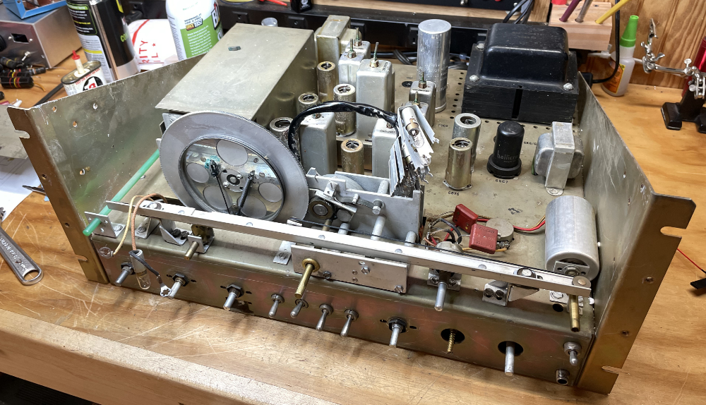
When I opened the lid of the receiver, the first thing I noticed was that the screw adjustment for one of the IF transformers was badly bent. Worse yet, the transformer was on the 2nd IF subchassis, meaning the subchassis would have to be removed in order to remove the IF transformer to fix it. I searched the web for hints on how to do this and found detailed instructions from K3MSB (Thank You!).
Left, is the underside of the subchassis with the offending IF transformer in the upper left (T5). Center, the transformer has been removed. Right, the ferrite slug had been damaged when the threaded adjustment was bent. Finding a suitable replacement slug seemed impossible, so I epoxyed a 4-40 screw to the remaining slug and hoped that it would still work. By puttng the slug and the tip in a short piece of 1/4" plastic straw, the parts were kept in alignment while the epoxy cured.
I must admit that I had the subchassis out and reinstalled three times because there was always something I had overlooked that required taking it apart again. But now I'm experienced with the process, not that I look forward to doing it again.
After several weeks of frustration with trying to get a signal through the receiver, and using a less than ideal signal generator to align the IF stages and to get the subchassis 2nd oscillator working, I finally had success. The SX-101A works and now needs a good alignment with a precision signal generator (ordered one!).
Swan 350 Transceiver
The 350 was in good shape when purchased, but I had no idea when it was last used. Many older pieces of ham equipment found on ebay are sold "for parts or repair" because of age and this was no exception. It took some time to find a compatible power supply so in the meantime I went over it and replaced some outdated parts.
Replaced the old electrolytic caps and some of the other suspect capacitors.
I had a hard time finding a schematic that was high enough resolution to enlarge to a size I could read. I think many of the free, downloadable manuals and schematics are copies of copies, and the inevitable lack of focus results. I also wanted a complete schematic instead of the 4-pages of schematics found in my downloaded Swan manual. Using Affinity Designer, I drew over the pieced together schematic I had and slowly put in the details of component values as I was able to find them. There were a number of changes/updates made by Swan during production so there may be some details that I've overlooked, so no guarantees. My transceiver is the 350, but later models were made with designations of A, B, and C. But even among the (just) 350, there were circuit changes during its production run. I've included my 350 schematic here. Click on the image if you want to see a higher res image.
Ameco CN50 6 Meter Converter & Power Supply
The Hallicrafters SX-101A has a "Converter" band that is calibrated for both 6 an d2 meters and tunes 30.5 to 34.5 MHz for use with a third-party converter for either the 2 meter or 6 meter ham band that can output to these frequencies. I've read that this wasn't such a great addition to the "A" model as it eliminated the 160 meter band and didn't make such a hit with the ham community. I, however, think this is just what I need, so the search was on for a converter that could output to the frequencies required of the SX-101A. What I found was that the Ameco 6 meter converter could do this with the subsitution of a 19.5 MHz crystal and a few "tweeks." I found the CN50 model which had little nuvistor vacuum tubes that were known for low noise. This model sold new for a bit more the the standard vacuum tube model. Like a lot of gear at that time (1960's), the converter required an external power supply. I found the Ameco PS-1 power supply in rough shape but hoped that the transformer was intact, as the rest of the components would be fairly easily replaced.
A clear schematic for the CN50 can be found on the Ameco page.
The pics below show the rebuilt PS-1. I replaced everything except the 750 ohm / 5 watt resistor. The additional 5 watt resistor is intended to lower the output voltage because the original selenium rectifier reduced the DC voltage, so a new silicon diode rectifier would pass a higher voltage to the output. The Ameco converter requires 100-125VDC and the manual warns against the damage a higher voltage will do. When I connect the converter to the power supply through a Variac, I'll find out if that resistor is necessary.
The CN50 has antenna and output connectors that were once found on automobile radios. These connectors are a bit out dated so I intend to replace them with BNC connectors. I replaced the antenna one but I am waiting on an order for more to replace the output connector. Everything else in the converter looks ok, but testing will tell.
Heathkit DX-40
This is another hamfest "bargain" I couldn't resist. So many projects, so little time! I wanted to make this an AM transmitter and forego the CW. Everything I read about this transmitter was critical about the function switch, which regularly failed. This switch was used to switch from AM (or CW) to standby, and was prone to wear and failure. I wanted to install a PPT relay triggered by my D-104 mic to bypass the function switch, so I used the Google to research how others had done so. Unfortunately, I mostly found where folks had made the mod to the DX-60, which, while very similar, had important differences. My modifications can be found here.
Homebrew Projects
40 meter DSB Transceiver
This double-sideband transceiver is another project I found on Dave Richards AA7EE page (explanation and schematic here). It uses a NE602 mixer IC and a ceramic resonator and diode for tuning. It works on receive, and I am getting modulated transmitter output according to my oscilloscope, but I haven't as yet had any luck on the air for a quality of signal report. Hopefully soon.
The first image below shows the transmitter, RF filter and T/R relay. The other image shows the mixer, VFO and mic amp. On the lower left is an audio amp module I bought to supliment the audio output level on the main board (it wasn't loud enough).