Homebrew Receiver Page
Let's Give This Another Go...
June 2026
The receiver below (July 2024) worked ok but not to the level I had hoped. I have left all the documentation as part of my journey to make a quality communications receiver. Over the months after completion, I attemped to address some of the issues that it had with "birdies", ssb reception and others. It would sit on the shelf for months at a time and I would take it down occasionly to tinker with the issues. I removed the product detector circuit and built another circuit. I installed additional shielding around the LO and BFO. I had hum issues and I tried unsuccessfully to fine the cause. I would set it asside to attend to woodworking projects, and then monkey with it again.
Finally, I reasoned, the issues with the receiver were a result for poor layout and planning. If that was the case, the only solution was to begin all over again and build another HBR from scratch.
The original chassis size would have most likely been fine had I done a better job with the layout. But the area of the chassis that held the AM detector, product detector and the audio components was very tight and cramped. So my reasoning is to use a larger chassis. I have a huge chassis BUD AC-1428 (17"x15"x4") that is overkill, but would give me plenty of room to plan a layout that would (hopefully) avoid some of the problems of the past project. Something a bit smaller would have been ideal, but this sure beat the cost of new. With this chassis there is a lot of real estate to work with.
A little knowledge is a dangerous thing. I have a pretty good foundation of electrical and electronics theory. I can describe various passive filters and figure out values to get reasonably close to a desired result. But I look for guidance for component values for vacuum tube RF circuits by reading about and looking at schematics of similar projects that others have done.
The schematic I’m working from is a conglomeration of circuits from a number of different HBRs found on the web and from ARRL publications. Attempting to outright copy a circuit for a tube project that someone has done 30, 40, 60 or more years ago is practically impossible; so many critical parts are long out of production and only obtainable through sheer luck. So I decided that I would try to use the parts that I ve a few already had on hand as much as possible. I have been amassing tube electronics parts for many years, mostly from swap meets and occasionally, eBay.
So the circuit I’m working from is a compromise, and I hope I’ve given it enough attention that the result is a communications receive that works and is something I am proud of.
The Front End
I need a 50 Ohm input to the 6BA6 pentode RF amp. I have a few 4-pin coil forms, so I want to avoid as much as possible, tapped coils that will require 5-pin coil forms.
HF Oscillator
A 6C4 will be used.
Intermediate Frequency Circuit
Double conversation is a must for a serious communications receiver. I have 85Khz IF transformers from the previous project (below), so I intend to use them. I have a 1500Khz transformer for the first IF and a crystal of 1502.75Khz (that is as close to 1500Khz as I could find) for the 2nd Mixer.
Product Detector
I will use a 7360 tube in this circuit as found in the article on Rob's web Using the 7360 in the HBR-16 and the HBR update found in the .jpeg here: W7QBR improvement for the original HBR16 . I have a couple of 7360s
AM Detector
Half a 12AU7 will act as the “Infinite Impedance Detector. ” I like the way it sounds - I mean the name
AGC/AVC
I liked the idea of separating the AGC for the IFs from the AGC for the RF stage after reading an explanation for why this is desirable. Half a 12AU7 will act as the AGC amp.
Noise Limiter
Circuit from HBR16-2007 by Lee Craner WB6SSW. Schematic is on the Emmittsfixitshop web page.
S-Meter
The previous project didn’t have an S-Meter but I wanted to incorporate one in this one, as it didn’t involve a big investment in parts and the chassis has an abundance of real estate to play with.
Audio Amp
The 12AX7 - 6AQ5 combination worked well in the previous version, so I’ll keep that.
Pictured (left) is the power supply and audio sections. The small filament transformer located in front of the power transformer is necessary because the filament rating on the power transformer wasn't enough for all 12 tubes. The second picture above is the BFO built in a small (4" x 2-1/4 x 2-1/4") aluminum box. I did eventually replace the 1.5A filament transformer with a 3A.
The chassis was so large that I had a hard time deciding on a layout. A narrow Sharpie to draw a layout and alcohol to wipe it out and redraw... over and over. I think I overcompensated because my first HBR had a pretty poor layout. In the end I felt like I did the best I could and started to punch holes for the detectors and noise limiter/avc. I did, however, continue to change much of the layout
Main Tuning Dial: I searched eBay to find a nice looking vernier dial and found two that looked good - a Millen 10035 slide-rule dail and a NOS Lafayette 180-degree vernier (which I didn't know existed). I decided to use the Millen and drilled out the front panel. I cleaned and repainted it and it looked good! However, I should have spent a bit more time working the mechanism, which worked but was way too stiff. After spending some time trying to work out the problems, I decided to put it aside and use the Lafayette dial. Of course the front panel was already drilled but I managed hide the pre-drilled holes and relocate the main tuning variable cap to underneath the very tall 4" high chassis. I planned to shield the cap.
After building the audio amp I tried testing it. All I got was silence. Troubleshooting, I found that the input to the 12AX7 was 0 ohms to ground, so a short somewhere. Maybe the coax from the pot to the tube had shorted when I soldered the shield ground. Unfastened the coax lead on the tube end and resoldered. Still a short. Potentiometer leads were a little hard to get at so I removed it from the front panel to more carefully exam the coax connection. Then I saw this:
 The center terminal was permanately grounded. Replacement necessary.
For me, a formidable Challenge!
July 2024
I have avoided building more complex radios for a long time, and instead have made a number of the more simple regenerative radios. It has been a combination of lack of confidence, as I have had little experience with IF circuits, and a lack of the required components necessary to build such complex radios.
Earlier this year I tried my hand at building a copy of the the classic All American 5 (AA5) broadcast band radio, a superhet with a couple of IF stages. Finding the necessary IF transformers suitable for vacuum tube circuits was a little difficult and a little expensive, since they are not produced anymore. But I found a couple, built the radio and managed to get it working. This was a confidence boost.
Always looking for a challenge, I started looking for a workable plan for a real communications receiver, one with double conversion and that could actually be used on the air. The recurring problem of finding suitable components raised its ugly head again. Again, finding IF transforms was the biggest challenge.
I searched through old issues of QST magazine (thanks to the World Radio History website) and found a number of aticles on building a communications receivers, but many required parts not produced anymore and very difficult if not impossible to find.
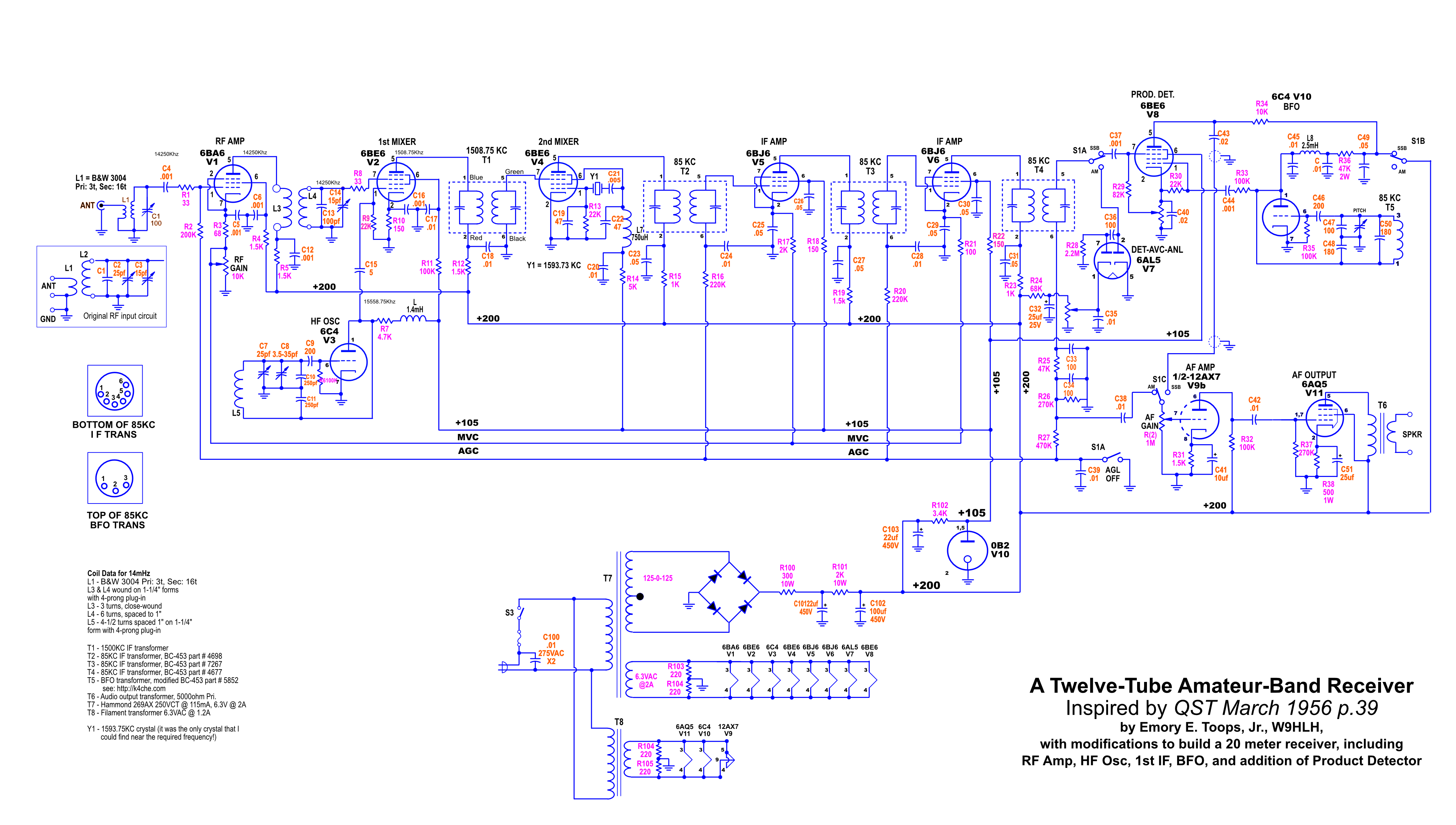
A March 1956 article by Emory E. Toops, Jr., W9HLH, seemed like a doable project as it used IF transformers from the WWII command receivers that are still floating around, many of which have been modified and are not contenders for restoration. The remainder of the required parts were obtainable or I had on hand, I began construction.
The schematic below is the latest of a series of changes (and hopefully,improvements) over the original circuit. It has evolved for several reasons, including difficulty in find some components, replacement of some circuits that didn't perform as expected, and additional capability, such as the product detector for SSB signals (which only works after a fashion, so more improvements are necessary). The circuit uses the 85Khz IF transformers from the BC-453 command receiver, as well as the BFO coil.
More explanation and information will be forthcoming...
-----------------------------------
BFO
Finding an inductor for the low frequency BFO can be a problem. However, Mr. B Smith's - K4CHE - website on Military Radio and Boat Anchors was a very big help. Use the link for the HBR-14 Receiver Construction for many useful tips, including how to modify the BC-453 Command Receiver BFO coil for use in a relatively simple BFO circuit.
The modifications to the BFO coil from the BC-453 is explained in detail. Here is a photo of the coil/capacitor assembly with the shield removed:
Something I wish I had done that that Mr. B. Smith recommended, is to build the BFO first (in a shield) and construct the rest of the radio around it. As a result, I ended up with a less than ideal chassis layout. I built the power supply and audio section first, which is often recommended so that the radio is created backwards and each subsequent section can be tested before moving on.
January 2026
It's been a while since I got back to this project. It did, in fact, work but not as well as I had hoped. I ended up putting a 6BE6 product detector circuit that seemed to work ok, but it was a rather poor craftsmanship and somewhat querky. I used the 6C4 oscillator tube location for the 6BE6, so I had to put the 6C4 under the chassis, as there was little room on top that wouldn't have involved long leads. The noise limiter circuit (part of the 6AL5) did't work at all. And, furthermore, there were a couple of "birdies" along the dial that probably resulted from poor shieding of both the local oscillator and the BFO. Ugh!
All this reinforces the poor chassis layout planning on my part. A lack of experience building superhet receivers was very evident.
So after completing my latest furniture project, I thought it might be good to look at the HBR project and see if I could overcome some of the shortcomings and realize the potential for a decent AM/SSB 20 meter receiver. Oh how naive!
The first thing I did was to remove all the components in the detector/noise limiter, BFO and product detector circuits and rebuild them.