Regenerative Radios
Beginnings
Early radios used regenerative circuits and were very sensitive, meaning they could receive weak radio stations. However, they were fiddly, requiring the operator to work with the dials and controls to listen to the stations they received. Regen radios were fairly simple to construct, perfect for the home builder, and many people did make their own radios. A whole movement developed out of the home built radios, including magazines, stores and the amatuer radio hobby. Later, when superheterodyne radios were introduced, the regens mostly fell out of favor because this new kind of radio was much more user-friendly.
Today, regen radios are perfect for the radio hobbyist and there are hundreds (maybe thousands) of websites with regen circuits and instructions for building your own.
Coil Winder
In the December 2017 DYIODE magazine, a DYI electronics publicaton out of Austrailia, the feature article was about constructing a coil winder based on an Arduino microcontroller. There were a number of 3D printed parts involved and it used stepper motors to both turn the coil winding armature and the wire follower. It looked like a good project. Since I had the parts on hand, I incorporated a turns counter and display.

The "Ultimate" Ultimate Regen
March-April 2022: I'm a sucker for regen radio projects, and when I saw this one I had to give it a try. NRQ-62 The Ultimate Regenerative Receiver by Jim Stoneback K4XAF. It's not too complicated but has plenty of knobs and dials, a requirement for a good project.
The article/webpage has three schematics and the project is constructed with two separate chassis. Most of the circuit is based on articles in Electric Radio Magazine (vols. 51-53) by Bruce Vaughan NR5Q.
https://www.ermag.com
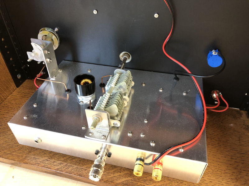
The power supply and audio PA chassis is on the left and the detector and pre-amp chassis is on the right. I'm waiting for a speaker grill so the blue tape is for aligning the mounting holes. The image on the right is the detector chassis. The swinging "tickler coil" is on the left. I use my laser cutter (Glowforge) to cut mounting brackets for almost everything. A hot-wire heater to bend the acrylic makes short work of making the brackets. As you can see, I've used this technique to mount the two variable caps as well as the shaft for the moving coil.
Schematics, more pics and descriptions will soon appear here.
My "Ultimate" Regen
Wandering the intertubes, I found a website by Dave Richards AA7EE, a ham radio enthusiast, who has built a number of amazing shortwave radios. His workmanship and skills are inspiring. One of his projects, the Sproutie MK II regenerative short wave radio is about the best example of the genre I have seen. I had to try to make a regen radio based on his design. I was sure that I didn't have the experience (and probably the skill) to come up to the level of Mr. Richards, but I was going to give it my best.
This is my attempt. I used the same circuits and a lot of Dave Richards ideas, so there isn't much new here. The radio works quite well and I am still making coils to try it on other shortwave bands.
Here are a few photos of the result,.
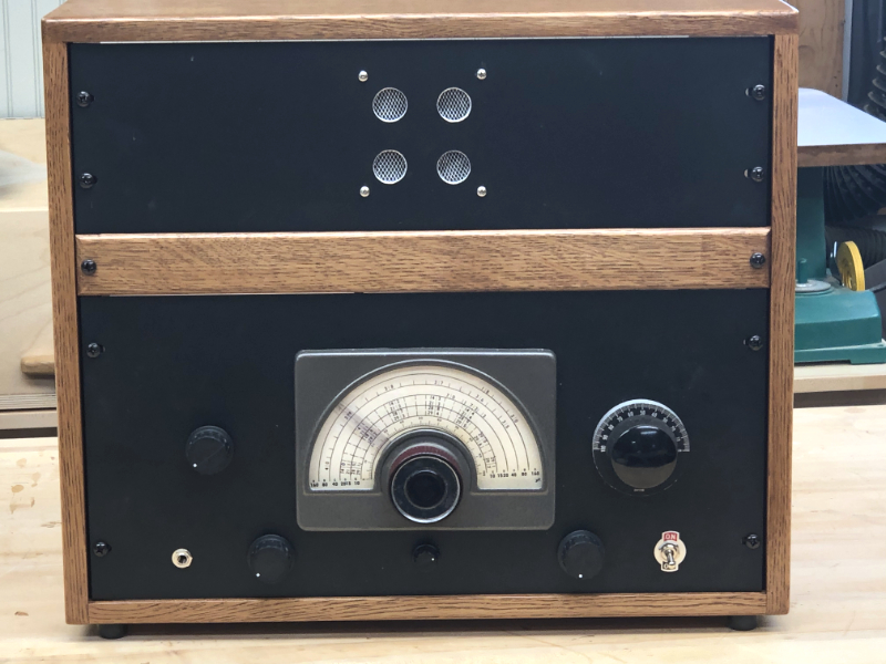
The regen control is left of the main tuning dial and on the right is the large vernier bandspread control. At the bottom of the front panel, left to right, is the phone jack, volume control, rf gain, audio filter selector, and power switch. In the second photo, the 10-turn regen potentiometer is the blue thing in the upper right.
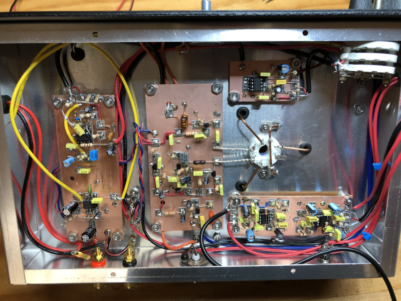
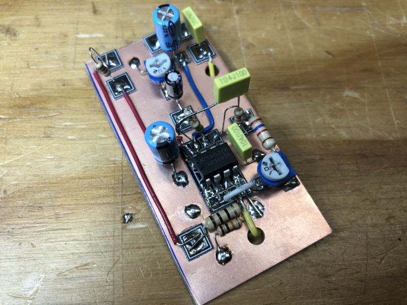
In the third photo, the audio amplifier and one of the audio filters are on the left board. The RF board is center, and the board on the right contains two audio filters. The white tube socket is used for plug-in coils. A third audio filter board is top right. The forth image is the wide-band 20kHz audio filter board. All circuits were built following the "Manhattan" construction. My skill with Manhattan constructon is improving, but Dave Richards work looks more like sculpture he is so good.
40 Meter Ham Band Regen
This is another Dave Richards (AA7EE) regen receiver project, the WBR Regen Receiver . It uses two 2N3904 NPN transistors and a J310 JFET, with a LM386 audio amp. The circuit is available through the link above.
Again, the RF circuit was built using "Manhattan" method of building circuits. For those of us who don't have the wherewithall to make printed circuit boards, this technique works very well.
80 Meter Ham Band Regen
The simple regen pictured below (schematic here) was an exercise to see if I could gear down the variable capacitor using laser-cut gears. I cut out the gears, the front panel and pointer, and engraved details for the front panel with the Glowforge. I do all my vector design work with Affinity Designer. The gears were made using .svg files from this terrific site: Gear Generator . It works pretty well, but I can see that it wouldn't be too hard to make a spring-loaded lash-free split gear for more accurate tuning. But this would be overkill on this radio.