Downloadable Files
These are files that I've made to be able to either cut them on my Glowforge Laser cutter or 3D print them on my MakerGear M3 3D printer. The laser cutting files are in the .svg vector format created on Affinity Designer. The 3D printing files are in the .stl format and created in Pro/DESKTOP, a program by PTC that is not longer available. (Note: Pro/DESKTOP runs only on PCs, so I use Parallels and Windows XP Pro on my Mac Mini. In the early 2000s, I worked with PTC to provide Pro/DESKTOP to US schools for free for use in Technology classrooms. It's a shame that it is no longer available as it was very intuitive and kids in even middle school picked it up quickly. It was so successful that schools in Britain adopted Pro/DESKTOP for their required Design and Technology courses as part of their national curriculum)
Enclosure for 8-Digit Digital Display PLJ-8LED-H
Download Zip Files for laser cutting:
.svg File for Blank Back Panel.
I wanted to add a digital display to the Swan 350 transceiver. The enclosue is 5.5"W x 1.5"H x 2.75"D. The front and back panels are 1/8" Acrylic and the Top, Bottom and Sides are 1/4" Acrylic (the actual thickness dimensions are 0.118" and 0.231"). These files can be used on a laser cutter.
Here are files for a slightly larger box: 6.5"W x 3"H x 4.25"D. Again, the parts are sized for 1/8" acrylic front and back, and 1/4" sides and top/bottom. The front and back panels are blank except for holes for 3mm screws to fasten them to the box. I use a #39 drill bit and 3mm screws that self tap in a hole this diameter.Download Zip Files for laser cutting:
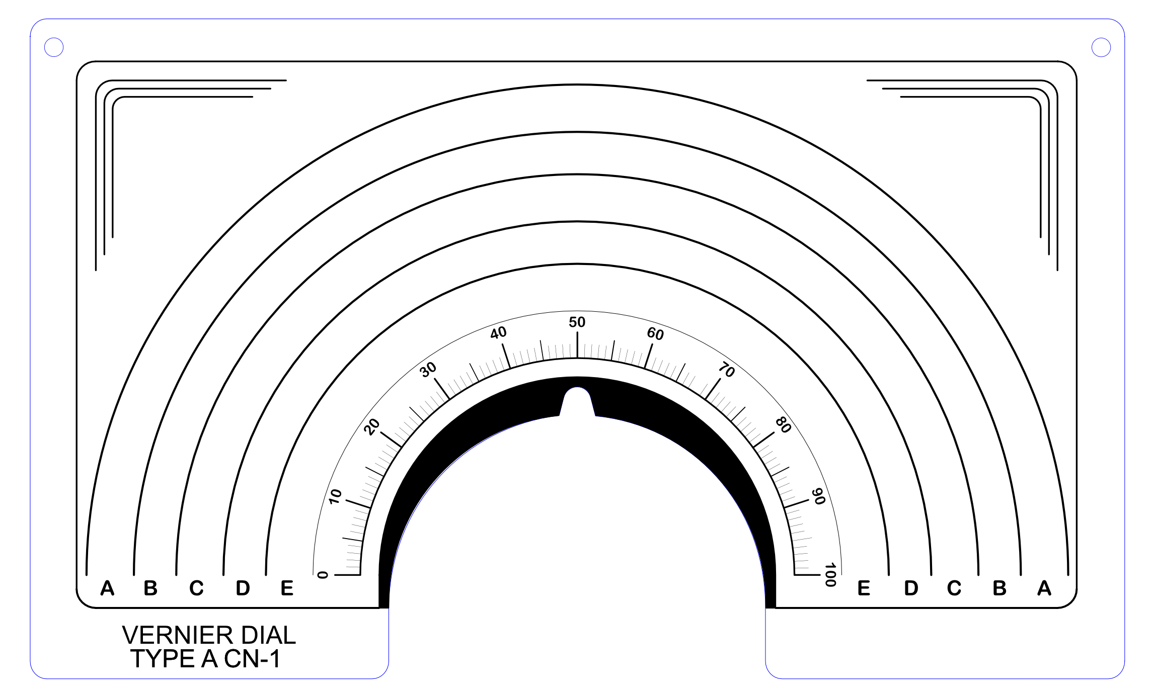
National Vernier Dial Type A CN-1 Insert
Download: .svg File for Printer or Laser Cutter.
I bought the National Vernier Dial on eBay. The actual dial and mechanism were in very good condition but the paper inert was yellowed and dirty, I guess from being decades old. I used Affinity Designer to replicate the insert, only leaving out the National logo since I didn't think I had the right to reproduce that. You can download a high res JPEG image or a SVG vector file. Printing on card stock is better than regular paper.
The actual outside dimensions are 7.25" X 4.25". Right-click on image to download jpeg. Blue lines are cut lines.
Dewalt Router Base
Download: .svg File for Laser Cutter.
Fits Dwalt Router DW621. The base covers the entire base of the router and should be made of 1/4" clear acrylic. The blue and black lines are cut lines. The red lines are construction alignment and centering lines and should be ignored.
You will need to countersink the screw holes in the base plate. the router will rapidly fill with saw dust if you do not connect it to a vacuum.
Astatic D104 Mic Element Conversion
Download: .svg File for Laser Cutter.
The adapter is used to put a Kobiton microphone element in an Astatic D104 microphone. Use 1/4" acrylic. The blue and black lines are cut lines, blue first, black second. The red lines are construction alignment and centering lines and should be ignored.
The adapter is the white acrylic ring. The Kobiton 25LM024 element press fits into the ring. The black rubber pieces centering the ring are placed to allow the screws holding the front and back plates together to pass through the assembly. The Kobiton element is available on ebay and several other vendors on the web.
Arduino UNO Base
Download: .svg File for Laser Cutter.
The base is used to fasten an Arduino UNO microcontroller to a metal or other base. Use 1/8" acrylic. The black lines are cut lines. The red lines are construction alignment and centering lines and should be ignored. The green line is just to orient the Arduino UNO. Holes to mount the Arduino UNO to the plastic are sized to use M3 metric machine screws. The screws will cut their own thread, so no need for nuts.
LCD 128x64 Mount
Download: .svg File for Laser Cutter.
It isn't easy to mount these small LCD screens. This file is useful when you want to mount these screens behind the front panel of a radio, VFO, etc. Use 1/8" acrylic. The blue and black lines are cut lines, cut blue first, black second. The red lines are construction alignment and centering lines and should be ignored.

RF Coil P-C70-OSC Mount
Download: ZIP.stl File for Coil Mount.
Finding new adjustable RF coils is difficult. I needed a substitute for the Miller 70-OSC coils for a project but couldn't locate any. This oscillator coil P-C70-OSC from Antique Electronics Supply was a good substitute. However, these coils have no method of mounting, so I 3D printed mounts available here.1/4" Shaft Coupler
Download: ZIP.stl File for Shaft Coupler
Building a tube transmitter, I needed an 1/4" insulated shaft coupler. I wasn't about to pay $25 or so for Miller or Johnson coupler on ebay, so I 3D printed one. Although the aforementioned couplers allow a bit of flexibility in shaft alignment, they are just not worth the price.
If you decide to print one of these, you will need to ream out the 1/4" hole because the 3D printer, while close, doesn't print exactly the diameter needed. I suggest you start with a 13/64" drill bit and then use the 1/4". That way, you can hold the coupler by hand and it won't be grabbed by the drill and twist in your hand. The set screw holes are also slightly undersize, so use a No. 36 drill bit and then tap with a 6-32 tap. Use sets crews that are about 1/4 long so you have enough "bite" to keep from stripping the threads.
Also, there is no reason why you can't use the .stl file for other size shaft holes, such as for a 1/4" to 3/8" adapter.