Schematics Page
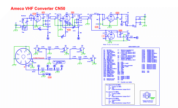
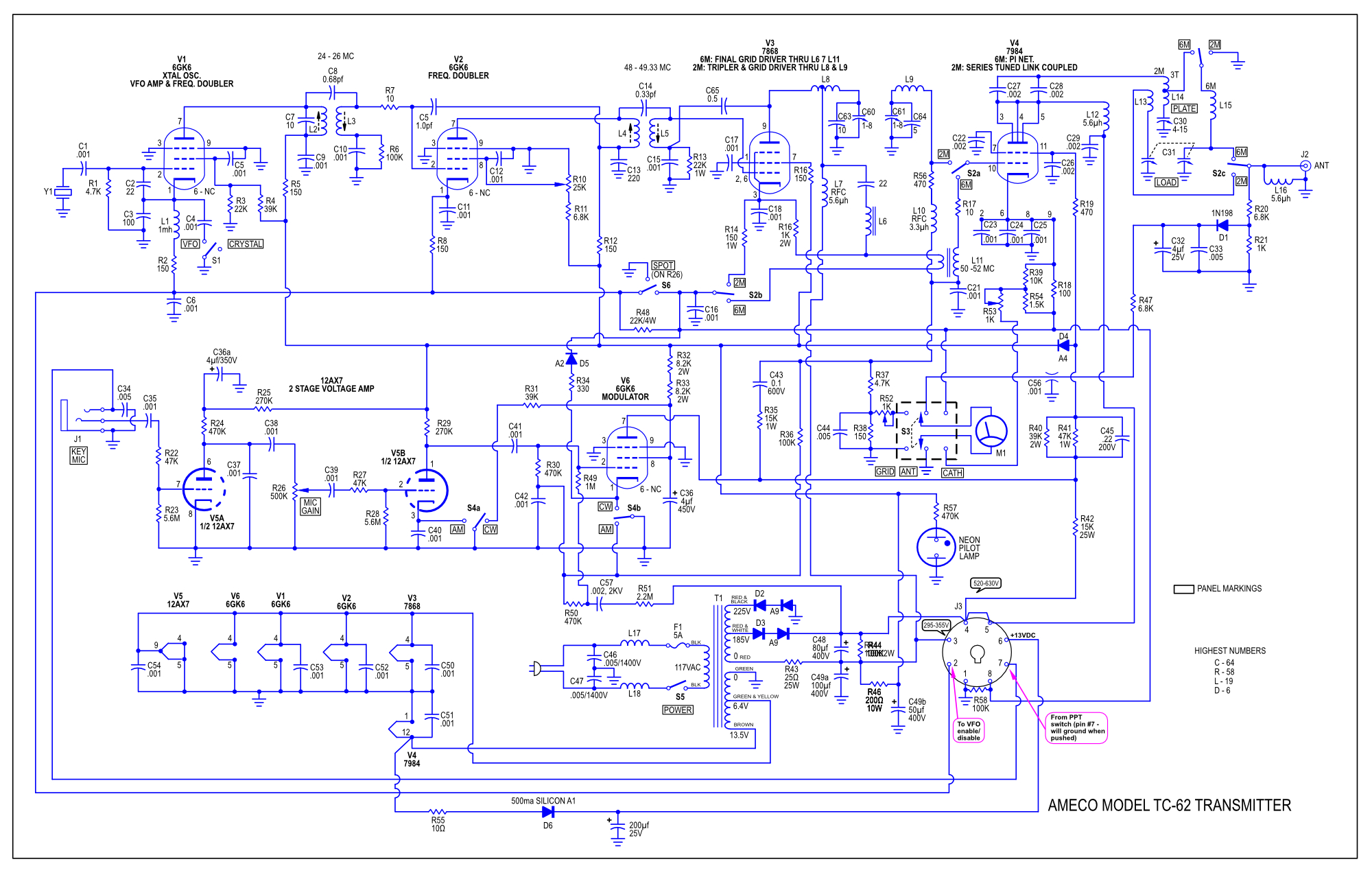
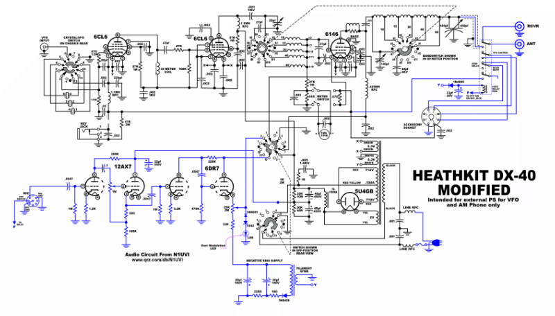
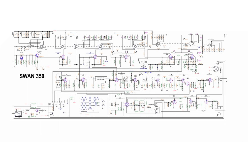
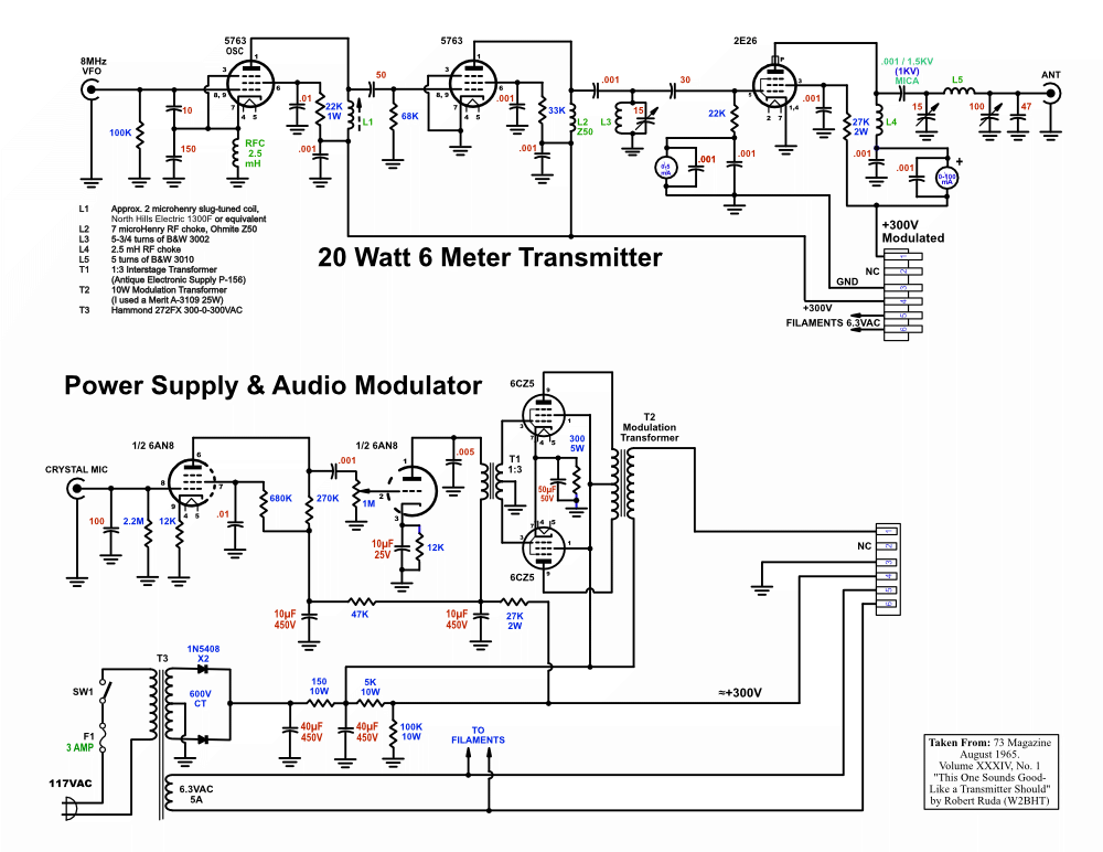
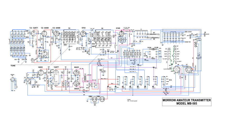
The following schematics are drawn with Affinity Designer, in most cases, using the original schematics from the manufacturer. Higher resolution images are available by clicking on the schematic.
I use Affinity Designer (AD) to draw the schematics as well as creating files for laser cutting and engraving. It's relatively inexpensive ($70) and very powerful. There are dozens of tutorials, but for drawing schematics one only needs to know a few commands.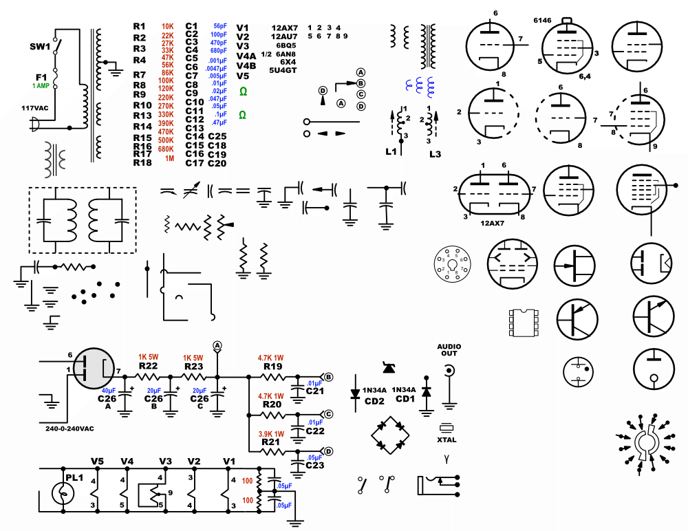
Here is a file of common electronic schematic symbols I've created in AD if you can use them.
Download the AD file: SchematicParts.afdesign.zip
OR...
Download the PDF file: SchematicPartsPDF . If you open the PDF file in a vector-type program you should be able to copy and paste each component.
Disclaimer: No guarantee of accuracy is implied, although I have made every effort to faithfully reproduce the original schematic except where I have modified the orginal circuit.
Hammarlund HQ-170A - Ham Band Receiver
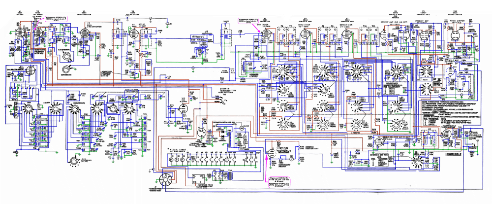
When I bought the HQ-170A it didn't work well and I wanted to trace some of the wiring. I also wanted to be able to mute the receiver when using a transmitter. It was unclear to me how the mute was being done and looking at the schematic in the manual didn't do much for clearing it up. So I redrew the schematic and made an attempt to clearify things in my mind. Well, I went a bit overboard and started coloring the grounds green and the B+ lines in red. It's a bit rough as it was a judgement call when B+ passed through resistors, but here is the result. Hope it helps someone.
